Production AI infrastructure
GPU Servers for AI: Hosting, Isolation and Production Readiness
A real client engagement. The engineering and the results are described below.
An enterprise AI vendor we worked with wins permission to pilot a new document service, but each rollout leaves expensive GPUs waiting for model artifacts. The business deadline turns a server specification into a question about storage, isolation and readiness.
Request a time through the inquiry form. A meeting is confirmed separately by email.
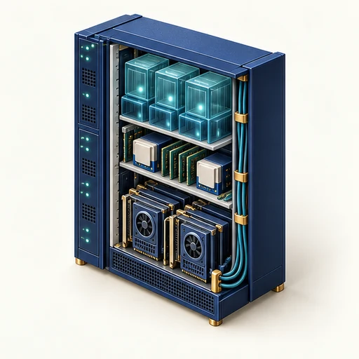
The business problem behind the technology
When does a paid GPU server become useful capacity?
The next release needs predictable preparation and recovery, without pretending a faster cold start alone establishes high availability.
Read the client engagement ↓Client engagement / Delivered results
The launch was waiting for the platform, not the GPU
An enterprise document platform we worked with runs 240 model-instance preparations a month across evaluation and release environments. Operators discover that an allocated device is often idle while software and artifacts become ready.
The constraint
The next release needs predictable preparation and recovery, without pretending a faster cold start alone establishes high availability.
The engineering decision
The team measures artifact transfer, CPU unpacking, driver compatibility and model loading separately. It chooses local model staging and a documented image/runtime contract, while preserving tenant isolation and a tested restore path.
The delivered outcome
Preparation fell from 45 to 15 minutes per instance. Across 240 monthly preparations, aggregate preparation time falls from 180 to 60 hours.
| Measure / unit | Before | After | Difference |
|---|---|---|---|
| Aggregate instance preparation time hours/month | 180 | 60 | 120 |
Aggregate instance preparation time. 240 × 45 / 60 versus 240 × 15 / 60. Parallel preparations mean this is not 120 hours off a calendar.
The conditions behind the results
- The 240 preparations and 45/15-minute times are the engagement’s operating values.
- Each instance loads the same artifacts and reaches the same real readiness condition.
- This ledger is separate from the eight-GPU placement example and does not claim a B200/B300 benchmark.
What this does not prove. Aggregate preparation time tracked the platform work delivered; overlapping instances were not counted as sequential delay.
Evidence to collect for your own decision
- Time every stage from allocation through successful model-ready requests.
- Test identity, storage permissions and isolation on the exact offered node configuration.
- Remove a failure domain and prove recovery with the required model available.
Key decisions
A production model depends on much more than a GPU. Follow the path from rack power and server hardware through the hypervisor, guest operating system and serving runtime, then test the storage, isolation and recovery assumptions that make the whole service dependable.
- Time every stage from allocation through successful model-ready requests.
- Test identity, storage permissions and isolation on the exact offered node configuration.
- Aggregate preparation time is not staff time, cash savings or an availability guarantee; overlapping instances must not be counted as sequential delay.
Follow the decision
Select a step to follow its reasoning, then continue into the technical chapters.
Problem → boundary → decision → evidence
Keep physical resources and provider-reported capacities in their proper scope.
Read every component and connection
- Inspect the node · Problem
- Keep physical resources and provider-reported capacities in their proper scope.
- Make the model ready · Decision
- Storage, drivers and warmup must work before capacity can serve.
- Rehearse recovery · Evidence
- Prove the failure domain and service objective you intend to support.
A conceptual decision map for this article, not a measured timeline, physical topology or a depiction of a specific client system.
Hover, focus or tap a component to inspect it. Motion adapts automatically to connection, device and accessibility signals; the component key remains readable without JavaScript.
Start below the operating system
The client’s document platform inventories the host and facility before promising that a device is ready for its pilot.
Real cloud examples make the boundary concrete. AWS currently documents p6-b200.48xlarge and p6-b300.48xlarge offerings with eight GPUs each. Its product table reports 1,432 GB and 2,144 GB of GPU memory respectively, alongside different host-memory and network capacities. These diagrams preserve that table’s scope; they are not live tenant telemetry or a claim that I operate these instances.
Do not substitute a DGX reference-system bill of materials for the cloud instance. NVIDIA’s DGX B200 guide lists 1,440 GB across eight GPUs, two fifth-generation NVSwitch devices and ConnectX-7 networking. Its DGX B300 guide lists eight 288 GB GPUs and ConnectX-8 networking. Provider-exposed memory, model allocations and reference-system specifications can differ; inspect the actual ordered configuration rather than silently reconciling unlike numbers.
A server combines CPUs, system RAM, GPUs, storage controllers, network interfaces, firmware and power supplies. PCIe and NUMA topology influence which CPU, memory bank and devices exchange data efficiently. A rack adds power distribution, cooling and network uplinks. These dependencies remain present when a cloud API hides them.
Verify rack power density, cooling compatibility, circuit redundancy, link capacity and the ownership of firmware updates before promising usable GPU capacity. Nameplate power is a planning limit, not measured energy. The facility must support the actual equipment and failover behavior, including maintenance conditions.
Facility
Power, cooling, physical access and network paths keep equipment available.
Host
Firmware, devices and the host or hypervisor establish the machine boundary.
Guest
A VM owns its kernel; containers may share that guest kernel.
Service
Drivers, runtime, model and application policy deliver useful requests.
A conceptual responsibility stack, not a universal boot sequence or security certification.
Published offering · p6-b200.48xlarge
Eight B200 GPUs · 1,432 GB reported GPU memory · 192 vCPUs · 2,048 GiB host RAM
Host and staging
Eight separate GPU memory domains
Scale up within the node
Scale out, storage and isolation
Host threads tokenize, prepare batches, run the serving scheduler and submit CUDA work. A vCPU count is not a GPU execution-lane count.
Read every component and connection
- Host CPUs · 192 vCPUs
- Host threads tokenize, prepare batches, run the serving scheduler and submit CUDA work. A vCPU count is not a GPU execution-lane count.
- Host DRAM · 2,048 GiB
- CPU-addressable memory stages data and hosts application state. It is separate from GPU HBM; copies, mappings and supported direct-I/O paths have distinct costs.
- GPU 0 · B200
- One of eight B200 devices, each with its own memory and execution resources. This ordinal is a diagram label, not a hardware UUID or a claimed running allocation.
- GPU 1 · B200
- One of eight B200 devices, each with its own memory and execution resources. This ordinal is a diagram label, not a hardware UUID or a claimed running allocation.
- GPU 2 · B200
- One of eight B200 devices, each with its own memory and execution resources. This ordinal is a diagram label, not a hardware UUID or a claimed running allocation.
- GPU 3 · B200
- One of eight B200 devices, each with its own memory and execution resources. This ordinal is a diagram label, not a hardware UUID or a claimed running allocation.
- GPU 4 · B200
- One of eight B200 devices, each with its own memory and execution resources. This ordinal is a diagram label, not a hardware UUID or a claimed running allocation.
- GPU 5 · B200
- One of eight B200 devices, each with its own memory and execution resources. This ordinal is a diagram label, not a hardware UUID or a claimed running allocation.
- GPU 6 · B200
- One of eight B200 devices, each with its own memory and execution resources. This ordinal is a diagram label, not a hardware UUID or a claimed running allocation.
- GPU 7 · B200
- One of eight B200 devices, each with its own memory and execution resources. This ordinal is a diagram label, not a hardware UUID or a claimed running allocation.
- NVLink fabric · GPU ↔ GPU
- The scale-up fabric connects compatible GPU peers for transfers and collectives. The runtime must partition work and enable the relevant paths; summed HBM is not one automatic allocation.
- EFA networking · 3.2 Tbps aggregate
- EFA provides the scale-out transport between instances. NCCL and the supported transport stack coordinate collectives; inter-node networking is not the same link as NVLink.
- Local NVMe · 8 × 3.84 TB
- Local instance storage can cache datasets and model artifacts. The listed raw drive capacity is not durable object storage or a promise of the same usable RAID capacity.
- EBS path · 100 Gbps listed
- The product table lists EBS bandwidth separately from local NVMe and EFA. Volume provisioning and workload behavior still constrain achieved storage throughput.
- AWS Nitro · Virtualization / I/O
- Nitro combines specialized hardware and firmware for the EC2 isolation and I/O boundary. Guest Linux, NVIDIA drivers and application permissions remain distinct responsibilities.
- Local NVMe → Host DRAM: stage artifacts
- EBS path → Host DRAM: volume I/O
- Host CPUs → Host DRAM: host memory
- Host DRAM → GPU 0: supported device transfer
- AWS Nitro → Host CPUs: guest / I/O boundary
- GPU 0 → NVLink fabric: NVLink peers
- GPU 1 → NVLink fabric: NVLink peers
- GPU 2 → NVLink fabric: NVLink peers
- GPU 3 → NVLink fabric: NVLink peers
- GPU 4 → NVLink fabric: NVLink peers
- GPU 5 → NVLink fabric: NVLink peers
- GPU 6 → NVLink fabric: NVLink peers
- GPU 7 → NVLink fabric: NVLink peers
- EFA networking → GPU 0: collective transport
AWS product-table figures, checked September 8, 2026. This is a conceptual map of a published production offering, not access to a tenant, a live health feed or a guarantee of spare capacity. Ordinals 0–7 are diagram labels. Links show logical responsibilities, not proprietary board traces.
Hover, focus or tap a component to inspect it. Motion adapts automatically to connection, device and accessibility signals; the component key remains readable without JavaScript.
Published offering · p6-b300.48xlarge
Eight B300 GPUs · 2,144 GB reported GPU memory · 192 vCPUs · 4,096 GiB host RAM
Host and staging
Eight separate GPU memory domains
Scale up within the node
Scale out, storage and isolation
Host threads tokenize, prepare batches, run the serving scheduler and submit CUDA work. A vCPU count is not a GPU execution-lane count.
Read every component and connection
- Host CPUs · 192 vCPUs
- Host threads tokenize, prepare batches, run the serving scheduler and submit CUDA work. A vCPU count is not a GPU execution-lane count.
- Host DRAM · 4,096 GiB
- CPU-addressable memory stages data and hosts application state. It is separate from GPU HBM; copies, mappings and supported direct-I/O paths have distinct costs.
- GPU 0 · B300
- One of eight B300 devices, each with its own memory and execution resources. This ordinal is a diagram label, not a hardware UUID or a claimed running allocation.
- GPU 1 · B300
- One of eight B300 devices, each with its own memory and execution resources. This ordinal is a diagram label, not a hardware UUID or a claimed running allocation.
- GPU 2 · B300
- One of eight B300 devices, each with its own memory and execution resources. This ordinal is a diagram label, not a hardware UUID or a claimed running allocation.
- GPU 3 · B300
- One of eight B300 devices, each with its own memory and execution resources. This ordinal is a diagram label, not a hardware UUID or a claimed running allocation.
- GPU 4 · B300
- One of eight B300 devices, each with its own memory and execution resources. This ordinal is a diagram label, not a hardware UUID or a claimed running allocation.
- GPU 5 · B300
- One of eight B300 devices, each with its own memory and execution resources. This ordinal is a diagram label, not a hardware UUID or a claimed running allocation.
- GPU 6 · B300
- One of eight B300 devices, each with its own memory and execution resources. This ordinal is a diagram label, not a hardware UUID or a claimed running allocation.
- GPU 7 · B300
- One of eight B300 devices, each with its own memory and execution resources. This ordinal is a diagram label, not a hardware UUID or a claimed running allocation.
- NVLink fabric · GPU ↔ GPU
- The scale-up fabric connects compatible GPU peers for transfers and collectives. The runtime must partition work and enable the relevant paths; summed HBM is not one automatic allocation.
- EFA networking · 6.4 Tbps aggregate
- EFA provides the scale-out transport between instances. NCCL and the supported transport stack coordinate collectives; inter-node networking is not the same link as NVLink.
- Local NVMe · 8 × 3.84 TB
- Local instance storage can cache datasets and model artifacts. The listed raw drive capacity is not durable object storage or a promise of the same usable RAID capacity.
- EBS path · 100 Gbps listed
- The product table lists EBS bandwidth separately from local NVMe and EFA. Volume provisioning and workload behavior still constrain achieved storage throughput.
- AWS Nitro · Virtualization / I/O
- Nitro combines specialized hardware and firmware for the EC2 isolation and I/O boundary. Guest Linux, NVIDIA drivers and application permissions remain distinct responsibilities.
- Local NVMe → Host DRAM: stage artifacts
- EBS path → Host DRAM: volume I/O
- Host CPUs → Host DRAM: host memory
- Host DRAM → GPU 0: supported device transfer
- AWS Nitro → Host CPUs: guest / I/O boundary
- GPU 0 → NVLink fabric: NVLink peers
- GPU 1 → NVLink fabric: NVLink peers
- GPU 2 → NVLink fabric: NVLink peers
- GPU 3 → NVLink fabric: NVLink peers
- GPU 4 → NVLink fabric: NVLink peers
- GPU 5 → NVLink fabric: NVLink peers
- GPU 6 → NVLink fabric: NVLink peers
- GPU 7 → NVLink fabric: NVLink peers
- EFA networking → GPU 0: collective transport
AWS product-table figures, checked September 8, 2026. This is a conceptual map of a published production offering, not access to a tenant, a live health feed or a guarantee of spare capacity. Ordinals 0–7 are diagram labels. Links show logical responsibilities, not proprietary board traces.
Hover, focus or tap a component to inspect it. Motion adapts automatically to connection, device and accessibility signals; the component key remains readable without JavaScript.
Know what the hypervisor isolates
The next boundary is the machine the application believes it owns. Hypervisors and containers divide responsibilities in different ways.
A hypervisor presents virtual CPUs, memory and devices to guests and controls access to underlying resources. Different platforms implement this differently: KVM uses Linux virtualization support, while cloud providers may combine a hypervisor with specialized offload hardware. Bare-metal hosting exposes a different responsibility boundary.
A VM has its own guest kernel. Ordinary containers share the kernel of their host, which may itself be a VM. Namespaces, cgroups and container policies are useful controls but are not automatically equivalent to a hardware virtualization boundary. Choose tenancy and threat assumptions before selecting the packaging format.
Software ownership, from cluster to silicon
Kubernetes places the workload. The container stack exposes a device. CUDA and the driver submit work. GPU scheduling and execution happen below that boundary.
Cluster lifecycle and placement
Application and user-space libraries
Kernel and device boundary
Observe the real service
The scheduler chooses a suitable node using declared resources and placement policy. It does not place individual CUDA blocks, schedule warps or make an unready model useful.
Read every component and connection
- Kubernetes scheduler · Node / resource placement
- The scheduler chooses a suitable node using declared resources and placement policy. It does not place individual CUDA blocks, schedule warps or make an unready model useful.
- Device plugin / kubelet · GPU allocation
- A device plugin advertises supported GPU resources and participates in allocation. Kubelet starts the pod with the chosen devices. GPU sharing changes the resource contract.
- GPU Operator · Lifecycle controller
- The operator can manage drivers, Container Toolkit, device plugin, feature discovery and monitoring. This is a control-plane responsibility, not a mandatory hop for each tensor.
- OCI runtime / Toolkit · Container device access
- The configured runtime and NVIDIA Container Toolkit expose the permitted devices and libraries. Containers share their host kernel; a VM or bare-metal host sets another boundary.
- Serving framework · Batching / model / NCCL
- A serving engine schedules requests and calls framework/library kernels. NCCL coordinates supported multi-GPU collectives. Application queueing is distinct from GPU instruction scheduling.
- CUDA runtime / driver · libcudart / libcuda
- CUDA APIs manage contexts, streams, memory and launches. The user-mode driver interfaces with kernel support. Compatible machine code or supported PTX compilation is required.
- Linux NVIDIA modules · Devices / memory / I/O
- Kernel modules cooperate with the OS for device access, memory mapping and control. Linux permissions and isolation still matter; a container image does not replace the host kernel driver.
- Queues / GPU firmware · Device work submission
- Supported driver and firmware paths submit and manage device work. Firmware-mediated responsibilities vary with platform and driver; this is not a proprietary command-protocol schematic.
- Kubernetes scheduler → Device plugin / kubelet: placement / allocation
- Device plugin / kubelet → OCI runtime / Toolkit: start with devices
- GPU Operator → Device plugin / kubelet: manage plugin
- GPU Operator → OCI runtime / Toolkit: manage toolkit
- GPU Operator → Linux NVIDIA modules: manage driver
- OCI runtime / Toolkit → Serving framework: run workload
- Serving framework → CUDA runtime / driver: library calls
- CUDA runtime / driver → Linux NVIDIA modules: driver interface
- Linux NVIDIA modules → Queues / GPU firmware: submit / manage
- Queues / GPU firmware → SMs / memory / ALUs: device work
- SMs / memory / ALUs → DCGM + application telemetry: device signals
- Serving framework → DCGM + application telemetry: service signals
A typical Linux/device-plugin deployment, not a universal platform configuration. GPU Operator manages components; it is not on every inference request’s data path. Driver, CUDA, framework and hardware compatibility must be validated together.
Hover, focus or tap a component to inspect it. Motion adapts automatically to connection, device and accessibility signals; the component key remains readable without JavaScript.
GPU passthrough, MIG and sharing are not synonyms
Sharing the accelerator sounds economical until isolation and contention enter the discussion. You now distinguish passthrough, MIG and time slicing.
With device passthrough, a guest uses an assigned device through a supported driver and virtualization path. IOMMU protection and device isolation groups matter for DMA; peer devices, firmware and platform support can affect the boundary. Do not treat an unsafe passthrough workaround as tenant isolation.
On supported NVIDIA GPUs, MIG partitions particular compute and memory resources into supported instance profiles. It does not partition the entire server or remove host administration responsibilities. Time slicing schedules access to shared hardware; advertising more logical GPU allocations does not create more VRAM or equivalent hardware isolation.
| Method | What is allocated | What to verify |
|---|---|---|
| Whole-device passthrough | A supported physical device assignment | IOMMU grouping, driver support and reset behavior |
| MIG | A supported hardware resource partition | GPU generation, profile sizes, reconfiguration and tenancy |
| Time slicing / process sharing | Access to shared GPU execution resources | Memory contention, scheduling and isolation requirements |
| Containers | An application environment and resource policy | Kernel boundary, device exposure and permissions |
Separate scheduling capacity from serving capacity
The scheduler can count devices, but the service needs complete, usable replicas. The placement example shows why those are different answers.
A model replica using tensor parallelism may require several compatible GPUs together. For eight GPUs, a two-GPU reserve and two GPUs per replica, the arithmetic ceiling is floor((8 − 2) / 2) = three replicas. If the devices are in incompatible hosts or links, even that ceiling may not be achievable.
Check GPU memory per device, CPU and RAM for preprocessing, network bandwidth, storage access and placement constraints. A scheduler allocation is not a loaded model, and a loaded model is not proof of healthy latency under traffic. Readiness should reflect the state required to serve useful requests.
Inventory
Count compatible physical GPUs, not oversubscribed logical shares.
Reserve
Hold back the capacity required by the explicitly stated recovery plan.
This model does not divide VRAM into arbitrary slots or simulate a Kubernetes scheduler.
Available physical GPUs: 8; GPUs reserved for headroom: 2; Whole GPUs per replica: 2
floor(max(0, available − reserve) / GPUs per replica). Requires compatible GPUs in a usable topology. CPU, memory, power, model VRAM and failure-domain placement may lower this ceiling. Reserve alone does not establish high availability.
Change the example assumptions
The worked result is readable without JavaScript. Inputs become available when the local WASM model loads; constrained connections and devices retain the static example.
Storage and CPU can dominate cold starts
The team traces cold-start work because its preparation-time model depends on making the same artifacts ready sooner.
Model startup may include image retrieval, weight download, checksum verification, deserialization, device transfer, compilation and warmup. Separate those intervals. An ideal 40 GB transfer over a sustained 2 GB/s path already needs 20 seconds before other work; that is a lower bound with decimal units, not a startup measurement.
For an active model cache, fast local NVMe can remove repeated network retrieval when lifecycle and consistency rules allow it. It is not durable model ownership: keep versioned artifacts and recovery sources. Track cache misses, storage throughput, CPU bottlenecks and per-stage startup time instead of assuming every slow start is a GPU problem.
Price facility energy without double counting
The conversation reaches the facility bill. You keep measured energy, planning assumptions and bundled colocation charges from becoming the same number.
Power Usage Effectiveness compares total facility energy with IT equipment energy over a defined boundary and period. A planning estimate with 5 kW of average IT load and PUE 1.4 implies 7 kW including facility overhead. Over a 730-hour month at $0.15/kWh, that is $766.50. Real metering, tariffs and load shape determine the actual bill.
Do not multiply a colocation quote by PUE if its power charge already includes the same overhead. Identify whether billing covers reserved circuit capacity, metered energy, a rack bundle or another basis. PUE does not measure useful model work or total environmental impact; neither a lower PUE nor a lower GPU wattage alone proves a better service.
Design around the failure domain you can lose
A reserve looks reassuring until the whole host disappears. The recovery story must survive the actual failure domain, not merely a smaller allocation.
Two spare GPUs in the same eight-GPU host cannot recover the service if that host fails. A host, rack, switch, power circuit and availability zone are different failure domains. Place surviving capacity and data where the intended failure cannot remove them together.
Exercise a drain, an abrupt node loss, a missing model artifact, a slow storage dependency and a rollout overlap. Measure time to healthy capacity and the client-visible error or queueing interval. Backups need restore tests; redundant power supplies need genuinely independent upstream power to provide the intended protection.
Make production acceptance observable
The platform review closes only when readiness and recovery—not a server specification—support the customer pilot.
Track user-facing latency, errors, queue age and useful throughput alongside GPU memory, thermal or power throttling, device errors, CPU pressure and storage or network saturation. Correlate application traces with the particular model version, replica and host. GPU utilization is diagnostic context, not the service-level objective.
Document the owners of firmware, drivers, hypervisor, guest images, credentials, model artifacts and incident response. Gate releases on compatible versions and a reproducible rollback path. Hosting selection becomes much clearer once these responsibilities and recovery requirements are priced explicitly.
Questions behind the decision
What should an AI GPU server acceptance test include?
Test the complete path: artifacts, host resources, drivers, serving runtime, readiness and recovery. Name the exact device and node scope; a device count or nominal memory figure does not establish service capacity.
Are GPU passthrough, MIG and time slicing equivalent?
No. They divide assignment, partitioning and scheduling in different ways, with different isolation and contention properties. Choose from the workload and tenant boundary rather than treating every sharing mechanism as interchangeable capacity.